Packet Tracer Custom Devices
You should see categories that correspond to intermediary devices, end devices, and media. The Connections category (with the lightning bolt icon) represents the networking media supported by Packet Tracer. There is also an End Devices category and two categories specific to Packet Tracer: Custom Made Devices and Multiuser Connection.
Cisco Packet Tracer (CPT) is a powerful network simulator program developed by Cisco. With this simulator program, you can prepare for Cisco exams by building complex networks and improve your network knowledge. The purpose of using this software is to prepare for Cisco CCNA or CCNP exams.
What is Cisco Packet Tracer?
Cisco Router, Switch, Server, PC, Laptop is a free program that provides support for many more devices. And it is also very simple and easy to use. You can save the projects you have created and then open them again quickly. In addition, it is more convenient and faster than GNS3 because it does not force your computer over.
However, it is not enough to use Packet Tracer when preparing for CCNP exams. Therefore, you can choose GNS3 for more advanced IOS commands.
Who Can Use?
This network simulator program can be used mostly by students preparing for Cisco exams and anyone who wants to improve themselves in the field of networking.
Before developing a real network topology, you can make a design in Packet Tracer and create a more professional design. If you are an instructor, you can create network project activities for your students.
In short, if you want to improve yourself in the field of system and network, we recommend starting with this network simulator software.
General View
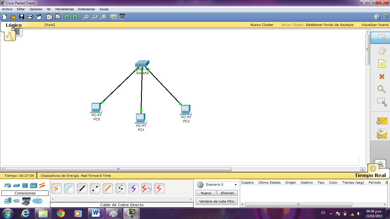
After installing the Packet Tracer simulator software, the first boot view is as follows.
| 1. | Menu Bar |
| 2. | Main Toolbar |
| 3. | Right Toolbar |
| 4. | Logical and Physical Study Area |
| 5. | Design Area |
| 6. | Realtime and Simulation Mode |
| 7. | Network Device Selection |
| 8. | Types of Network Device Selected Here. |
Main Toolbar
| New: | Creates a new project area. |
| Open: | Opens the previously saved project. |
| Save: | Saves the project. |
| Print: | Prints the current topology and configuration on the selected device and saves it as a PDF. |
| Activity Wizard: | Topology questions are created for students in educational institutions. |
| Copy: | Copies the selected device or any created object. |
| Paste: | Pastes the copied device or object. |
| Undo: | You can go back to the previous step. |
| Redo: | You can go to the next step. |
| Zoom In: | Zooms the workspace. |
| Zoom Reset: | Returns the workspace to the default. |
| Zoom Out: | Zooms the work area out. |
| Drawing Palette: | Creates square, rectangular, round, straight line, or random drawings. |
| Custom Devices Dialog: | Configures a custom network device. |
Right Toolbar
| Select: | Selects the device or any object on the workspace. |
| Place Note: | Used to create descriptive notes in the workspace. For example; IP address. |
| Delete: | Deletes the device or any object on the workspace. |
| İnspect: | Shows the output of protocols such as ARP, Routing, NAT of a working network device. |
| Draw Tool: | Drawing Palette tools are available here. |
| Resize Shape: | Resizes shapes drawn with the Draw Tool on the workspace. |
| Add Simple PDU: | In topology, it sends an ICMP Packet (Ping) between two devices. It can be used to test the connection. |
| Add Complex PDU: | In topology, detailed packets can be sent between two devices, source, and destination. |
Logical and Physical Workspace
Logical: The logical area is the main screen that you see when you first open Packet Tracer.
Physical: You can create a more detailed topology by switching to the physical field. For example; Main Building Connection.
Network Device Selection Area
| Network Devices: | This group includes Routers, Switches, Hubs, Wireless Devices, Security and WAN Emulation, which are commonly used in the network topology. |
| End Devices: | In this group, there are Desktop, Server, Laptop, SmartPhone, Printer, VoIP, TV, Analog Phone, Tablet, and Wireless devices. |
| Components: | Various components have added for detailed network design. These; Board (MCU and SBC Cards), Sensors, Alarm, LCD, Motor, Led are the components to be used in more smart home design. |
| Connections: | Commonly used cable interfaces are available. To mention these; |
Cable Types
| 1. Automatically Choose Connection Type | Used for automatic cabling of network devices. You can use this option if you do not know which cable to connect a Cisco Router to. |
| 2. Console | Console Connection is the type of connection to the computer or laptop Serial/USB interface and to the Router or Switch console interface. The console connection is used for the initial configuration. |
| 3. Copper Straight-Through | Connects network devices that operate on different layers in OSI or TCP network models. For example; PC-Switch, Router-Switch. |
| 4. Copper Cross-Over | Connects network devices that operate on the same layers in OSI or TCP network models. For example; PC-PC, Switch-Switch, Router-Router, PC-Router. |
| 5. Fiber | Fiber Optic cables, which provide high speed in data transmission, transmit data as light. It can be used on connections that require high data transmission. |
| 6. Phone | It is used for the connection of Modem or Phone devices. |
| 7. Coaxial | It is the type of cable used in old network topologies. Nowadays it is used in Cable TV broadcasts. |
| 8. Serial DCE | DCE Serial Cable is used when configuring Cisco Routers with the Serial Interface. In this type of cable, the clock rate must be specified. |
| 9. Serial DTE | DTE Serial Cable is used for connecting devices such as Routers. The data rate is not required for this type of cable. T1/E1 uses standard speed for connections. |
| 10. Octal | Octal Cable is a 68pin connector at one end and 8 RJ-45 terminals at the other end. The task can be used to create a terminal or access server. |
| 11. IoE Custom Cable | This cable type, which comes with the CPT 7 release, was developed to develop smart home solutions. |
| 12. USB | It is a USB cable that connects devices with a USB interface. |
How to Install It?
Packet Tracer is simple and easy to install on Windows, Linux, and even macOS. The .exe setup file is used for installation on Windows systems and the tar.gz file is used on Linux systems.
Cisco has created a GUI interface to simplify installation on Linux. The extension of this setup file is .run.
To install on Windows, Linux, and macOS, you can view our articles below;
Installation in Windows ⇒ Video
You can watch the video below to install PT on your Windows computer and also subscribe to our YouTube channel to support us!
Final Word
In this article, we have made a general description of Cisco’s free network simulator program and explained the most frequently used tool menus in the workspace. Using this software, you can create complex network topologies and better analyze Switching and Routing operations. Thanks for following us!
Related Articles
♦ How to Use Cisco Simulator
♦ How to Create a Network
♦ How to Configure DHCP
♦ Ubuntu Packet Tracer
♦ How to Configure Telnet
What is Packet Tracer?
Packet Tracer (PT) is a simulation software that is used to study complex concepts of the Cisco CCNA network level. With Packet Tracer you can design, build, configure, and troubleshoot using virtual equipment. Packet Tracer provides a simulation and visualization with real-time continuous updates from the network logic. We use Packet Tracer to explore concepts, conduct experiments and test our understanding, so it is very useful for lectures, group and individual labs, homework and competitions.
Features
- Logical and Physical Workspaces
- Real-time and Simulation Modes
- Global event list (packet sniffer); Adjustable Windows
- LAN: Ethernet (including CSMA/CD*), 802.11 wireless
- Switching: VLANs, 802.1q, trunking, VTP, DTP, STP, RSTP
- TCP/IP: HTTP, DHCP, Telnet, TFTP, DNS, TCP*, UDP, IP,ICMP, and ARP including IPv6
- Routing: static, default, RIPv1, RIPv2, EIGRP, OSPF (single and multiple area) and inter-VLAN routing
- WAN: Frame Relay, PPP, HDLC
- Multiuser Connection: to allow peer to peer collaboration
Note: Current version of Packet Tracer does not run in Native mode in Mac OS or Linux. Windows Emulators are required.
Logical Workspace is the primary workspace for creating networks of any size and CCNA-level configuration.
Physical Workspace promotes an intuitive interaction with physical devices, with physical layout and distance representation including intercity, city, building, wiring closet, and device views. They include a cluster function to group devices, a custom device creation tool, and an array of devices (routers, switches including a layer3 3560 switch, hubs, functional servers, Linksys gear, WAN clouds, a Multiuser connection and cable and DSL modems.) The functional servers support HTTP, DHCP, TFTP, and DNS services.
Real-time Mode models real-time protocol updates and medium-fidelity Cisco IOS CLI configuration of switches and routers.
Simulation Mode allows for a detailed study of protocol interactions.
The list of supported protocols has grown to now also include 802.11 wireless, VTP, DTP, STP,RSTP, HTTP, DHCP, Telnet (with SSH), TFTP, DNS, single and multiple area OSPF, and CDP. The list of protocols to filter in the Event List has increased to allow the user to filter on most of these additional protocols.
Global event list (packet sniffer): The packet sniffer in Packet Tracer allows students to see some of the same kinds of information that they would see with a commercial packet sniffing program, such as Wireshark. This functionality allows students to see just the amount of information that is appropriate for a CCNA level student without overwhelming them with the amount of information that would be seen in the commercial product.
The GUI has zoom view tools, edit functions (copy, paste, and undo), improved window management, and ability to show/hide link lights and device labels. All pop-up windows are treated as independent window units so they can be placed anywhere on the desktop and manipulated independent of each other. Windows can be maximized, minimized and accessed by taskbar buttons or the <Alt><Tab> combination. The user can have as many windows open as needed.
Multiple languages are supported. Instructions are included for self-translation into other languages. To locate these instructions, go to the Help file and click on Translation Process in the navigation panel.
Physical interfaces model realistic equipment set up including adding and removing components.
Knowledge representations offer discovery learning by enabling “what if?” scenarios using the simulation-mode and visualization features that allow the student to “freeze time”.
Activity Wizard enables instructors to create automatically scored practice activities and enables instructors and students to easily create and share network templates. New features have been added to Activity Wizard. These features include enhancements to the user interface, feedback on performance in completing an activity, assessment of user-created PDUs, and the addition of the Variable Manager. The Variable Manager enables the instructor to create multiple activities based on a single activity and the use of variables. These variables may be used in the activity instructions and initial values to create different correct answers each time.
Routers
Router Models:
- 1841, 2620XM, 2621XM, 2811, Generic Router-PT, Generic Router Empty
Switches
Switch Models:
- 2950-24, 2950T-24, 2960-24TT, Generic Switch-PT, Generic Switch Empty, 3560-24PS, Generic Bridge-PT
Hubs
Hub Models:
- Generic Hub-PT, Generic Repeater-PT
Wireless Devices
Wireless Device Models:
- Generic Access Point-PT, Generic Access Point-PT-A, Generic Access Point-PT-N, Linksys-WRT300N
End Devices
End Device Models:
- Generic PC-PT, Generic Laptop-PT, Generic Server-PT, Generic Printer-PT, IP Phone-7960
WAN Emulation
WAN Models:
- Generic Cloud-PT, Generic Cloud Empty, DSL-Modem-PT, Cable-Modem-PT
Custom Made Devices
Custom Models:
- 1841 WIC-2T, 2621XM NM-2FE2W (2) WIC-2T, 2821 NM-ESW-161 (2) WIC-2T, Generic Wireless PC
Multiuser Connection
- Multiuser Remote Network
Connections
Connection Models:
- Automatically Choose Connection Type, Console, Copper Straight-Through, Copper Cross-Over, Fiber, Phone, Coaxial, Serial DCE, Serial DTE
Common Tools
The Common Tools Bar contains tools you will use regularly to interact with the work space:
- The Select tool is used to drag, highlight and select devices
- The Move Layout tool is used to move the workspace
- The Place Note tool is used to add notes or labels in the workspace
- The Delete tool is used to delete devices and links
Zoom viewing tools
- ZoomIn (Ctrl+I) to zoom into the workspace.
- ZoomOut (Ctrl+U) to zoom out of the workspace.
- ZoomReset (Ctrl+T) to reset the zoom of the workspace.
Editing tools
- Copy (Ctrl+C) to copy the selected item.
- Paste (Ctrl+V) to paste the selected item.
- Undo (Ctrl+Z) to undo the previous action.
The drawing Palette tool (Ctrl+D) and Device Template Manager.
A Cluster function
- Cluster function will group devices into a cloud.
A Move function
- Move will take a device and move it into or out of a cloud.
Some Tips
- If you would like to create multiple instances of the same device, hold down the CTRL key before clicking on the device. Click in the workspace placing a new device with each click.
- To cancel the process of creating multiple instances, click on the device again. (You can also hit the ESC key or simply click on another tool.)
- Devices can be dragged to a new location. Multiple devices can be selected by clicking and dragging a selection box around the desired devices. You can also hold down the SHIFT key while you click on multiple devices you wish to make part of your multiple selections. Once selected, highlighted devices can be moved around as a unit.
- A multiple selection can also be deleted by clicking on the Delete tool. The Delete tool can also be used to delete one device at a time.
- Use the Move Layout tool in place of the horizontal and vertical scroll bars to reposition your topology if it gets too big or if other windows are blocking your view.
- Use the Place Note tool to add information directly to the topology instead of using the Network Information window.
- The Inspect tool allows you to look at a device’s table such as the ARP, MAC and routing tables.
- At any point, you can save your topology using the Save button on the tool bar or the Save command from the File menu. Be sure to save it with the .pkt extension.